← Work

01

Tour Gulliout

MSc Thesis — Facade Renovation

Year

2023

Location

Lyon, France

Role

Lead Researcher & Designer

Client

Tour Guillot et auditorium Bourdeix (ex-CIRC), Reinventing Cities Competition

Team

Giandomenico Azzone, Konstantin Loshkov — MSc thesis, Politecnico di Milano. Advisor: Prof. Masera Gabriele

Tools

GrasshopperRhino.Inside.RevitRevitPythonANN
Tour Gulliout

Overview

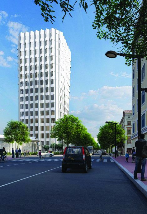
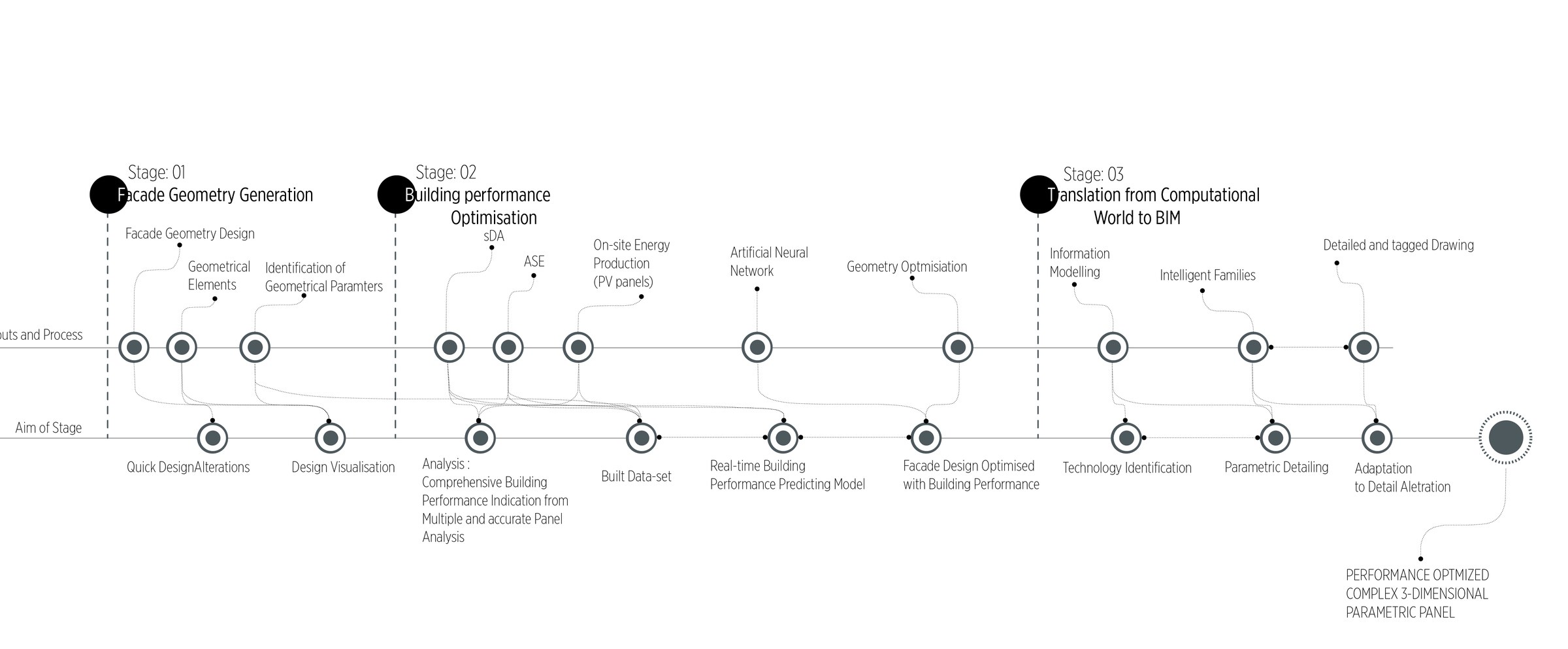
The subject of this MSc thesis at Politecnico di Milano was a 1972 office tower in Lyon — the former headquarters of the International Agency for Research on Cancer at 150, cours Albert Thomas. The building’s flat, repetitive curtain wall had deteriorated both technically and visually, disconnecting the tower from its urban context. The Reinventing Cities competition brief called for a complete envelope renovation. The response was a three-stage parametric workflow: geometry generation, solar performance optimisation with machine learning, and automated BIM translation to fabrication documentation — each stage feeding the next in a closed loop.

Site context map — Tour Gulliout location in Lyon city centre
Site — the tower at 150 cours Albert Thomas in Lyon. The Reinventing Cities brief required an envelope strategy that responded to the building's prominent corner position and mixed urban context.
Three-stage methodology diagram: Facade Geometry Generation, Building Performance Optimisation, Translation from Computational World to BIM
Methodology — the three stages of the workflow. Each stage produces an output that becomes the input to the next: geometry feeds the performance analysis, and the optimised geometry feeds the BIM translation.

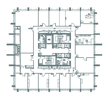
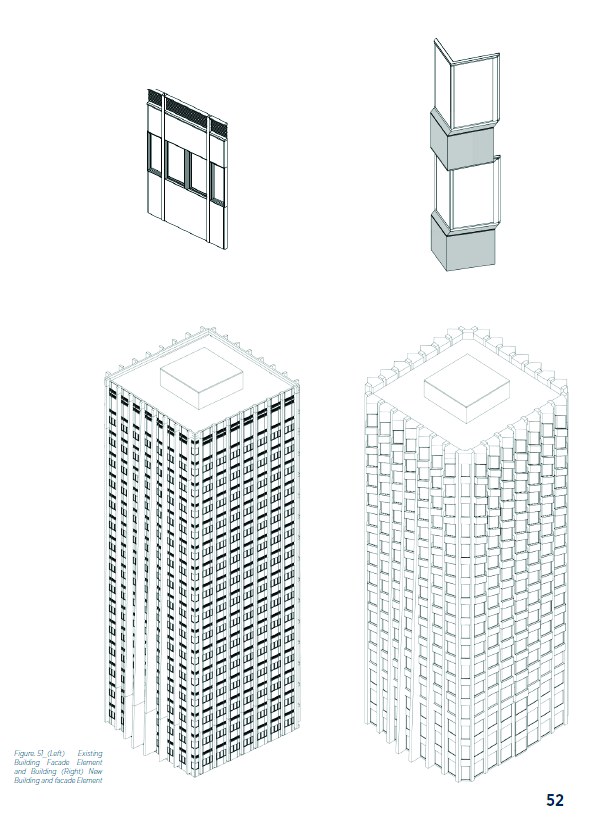
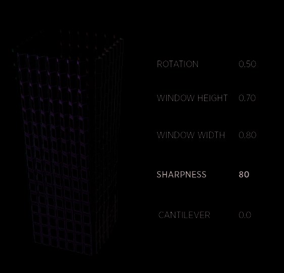
Stage 01 — Parametric Geometry

The existing facade was a standard flat curtain wall — a uniform bay grid with no depth, no solar shading, and no response to orientation. The renovation replaced it with volumetric panel bays controlled by five continuous parameters: rotation angle, window height, window width, corner sharpness, and cantilever depth.

Existing building floor plan — flat orthogonal curtain wall
Existing floor plan — the uniform flat curtain wall, with no differentiation between orientations and no facade depth
New floor plan with parametric rotated bay elements projecting from the building perimeter
New floor plan — the parametric bay elements project outward and rotate, creating a scalloped perimeter that produces self-shading and differentiates solar exposure by facade
Axonometric comparison: existing flat facade element (left) versus new volumetric parametric bay element (right)
Element comparison — existing flat panel assembly versus the new volumetric parametric bay. The new element introduces rotation, projection depth, and a controlled overhang at each bay, adapting independently across every elevation of the tower.

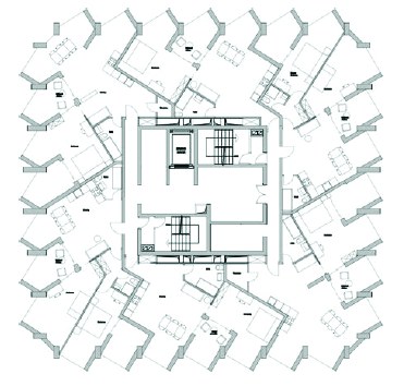
Every parameter remained live throughout the design process. Changes to performance targets propagated automatically into facade geometry via the Grasshopper definition — eliminating the manual update cycle that typically makes iterative facade design expensive.

Parametric model with live parameter panel showing rotation, window height, window width, sharpness, cantilever values — dynamic form variation across the full building volume
Parametric design space — one configuration from the solution space sampled to train the neural network. Each combination of the five parameters produces a distinct facade character and a distinct set of daylight performance values.

Stage 02 — Performance Optimisation

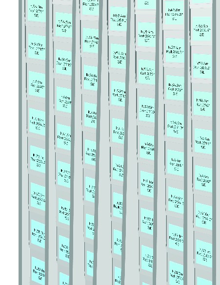
Solar performance was evaluated using Spatial Daylight Autonomy (sDA) and Annual Solar Exposure (ASE) — industry-standard measures of daylight quality and glare risk respectively. Running a full simulation for every candidate geometry was not feasible. The solution was to build an Artificial Neural Network trained on a targeted simulation dataset, then use the ANN as a real-time performance predictor in place of the simulation engine.

ASE pass/fail distribution across all four building elevations after optimisation
ASE analysis — pass/fail distribution across all four elevations after optimisation. The pattern reflects solar exposure geometry: south and west faces carry a higher proportion of failed zones; north and east elevations maintain ASE compliance across nearly all bays. Panel-by-panel optimisation allowed each zone to be tuned independently rather than applying a single facade rule to the whole building.

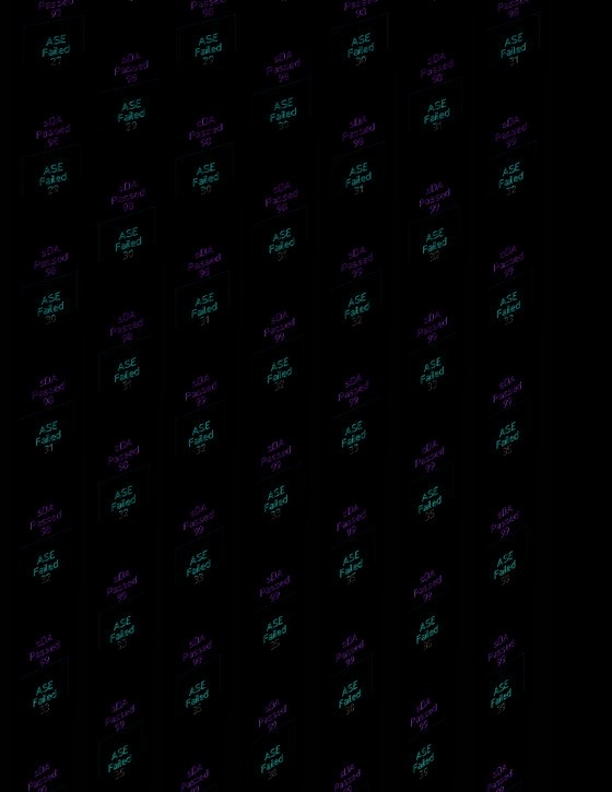
The trained network could evaluate thousands of panel configurations in the time a single simulation would take. This made it possible to optimise each of the tower’s 400+ panel bays independently — maximising sDA while keeping ASE below the 10% threshold — rather than finding a single global compromise geometry.

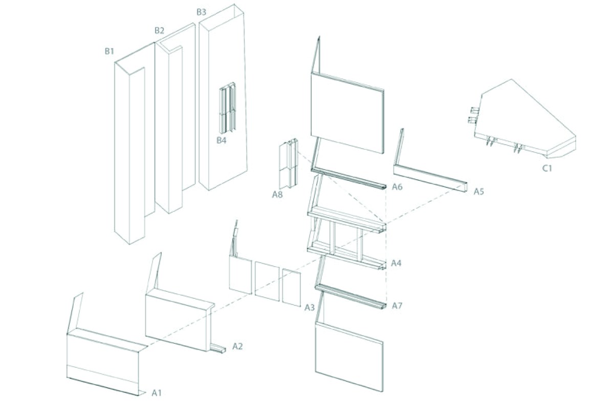
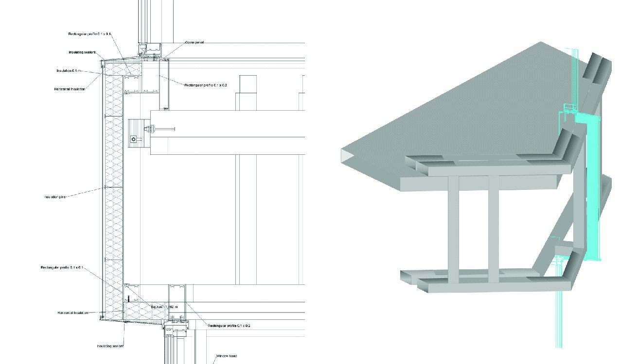
Stage 03 — BIM Translation

Optimised geometry was translated into a fully documented Revit model through Rhino.Inside.Revit. A set of parametric line-based detail families was developed whose dimensions are directly linked to the 3D facade geometry: any change in the computational model updates the construction details automatically, closing the loop between design and fabrication documentation.

Exploded axonometric of the facade panel assembly — sub-components labeled A1–A8, B1–B4, C1
Intelligent family — the parametric facade panel decomposed to its fabrication components. Each sub-element is tagged and schedulable, while adapting automatically to the varying rotation and depth values of its position on the tower. The family contains the full assembly logic: structural frame, glazing, cover panel, and connection hardware.
Tagged facade panel schedule in Revit — each bay listed with its geometric parameters h, Rot, Pat
Panel schedule — every bay tagged with its geometric parameters. The schedule drives fabrication: each row represents a unique configuration, automatically numbered and keyed to the construction drawings.
Construction section detail drawing and 3D model of the facade panel connection system
Construction detail — section and 3D model of the panel connection system. The detail family updates when facade parameters change, eliminating the manual redrawing that typically makes parametric design documentation expensive.