Overview
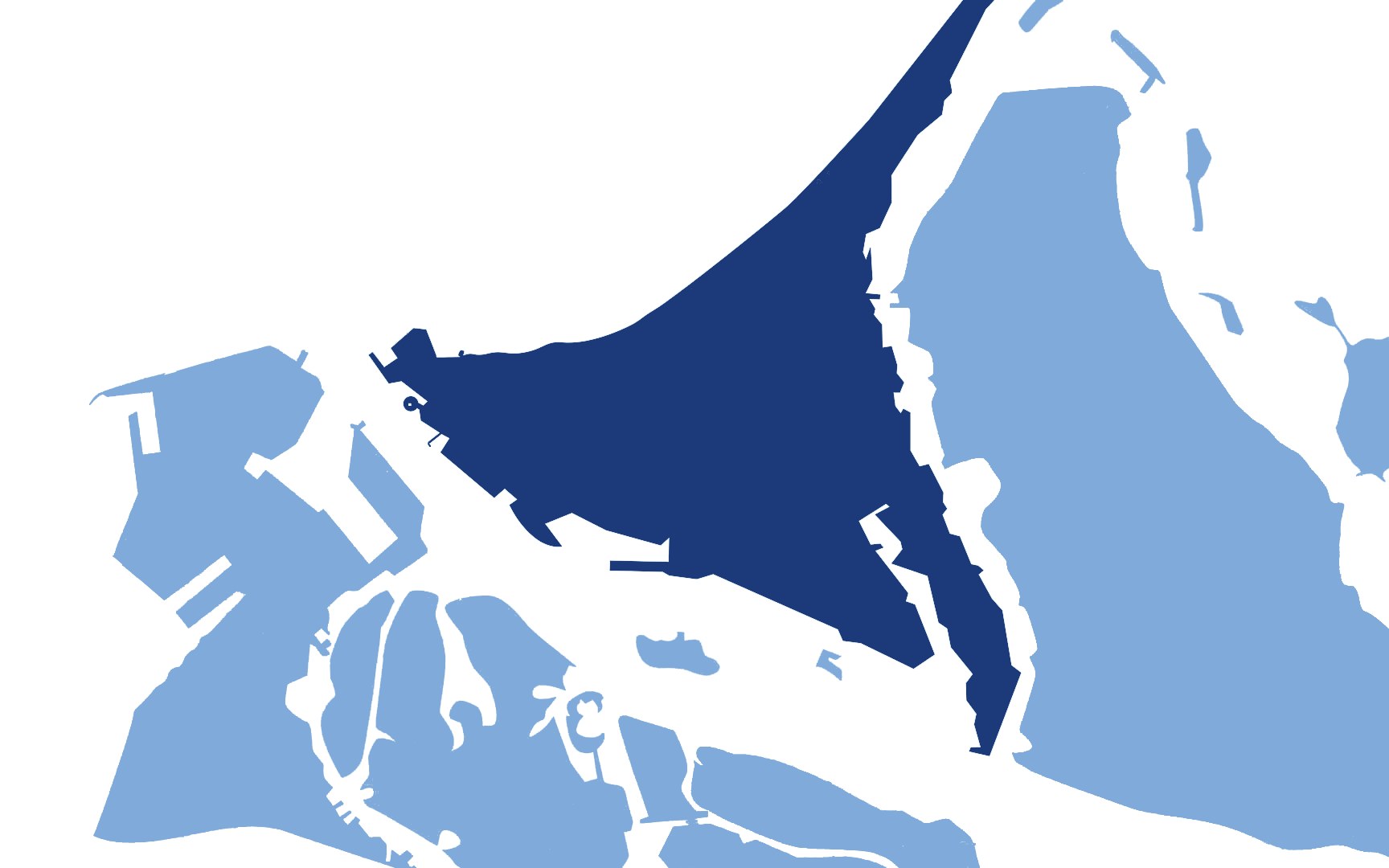
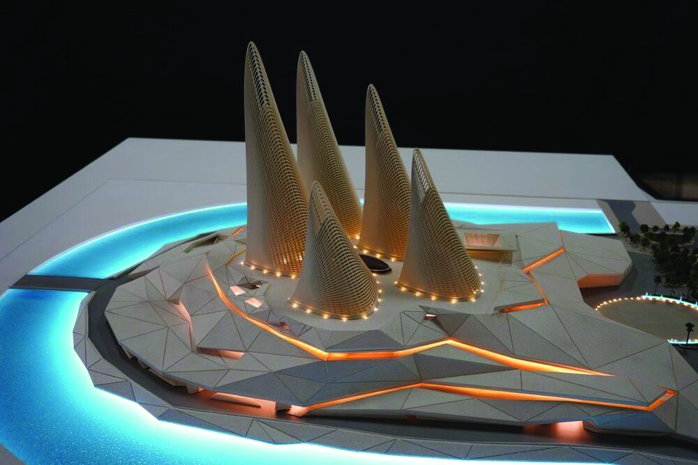
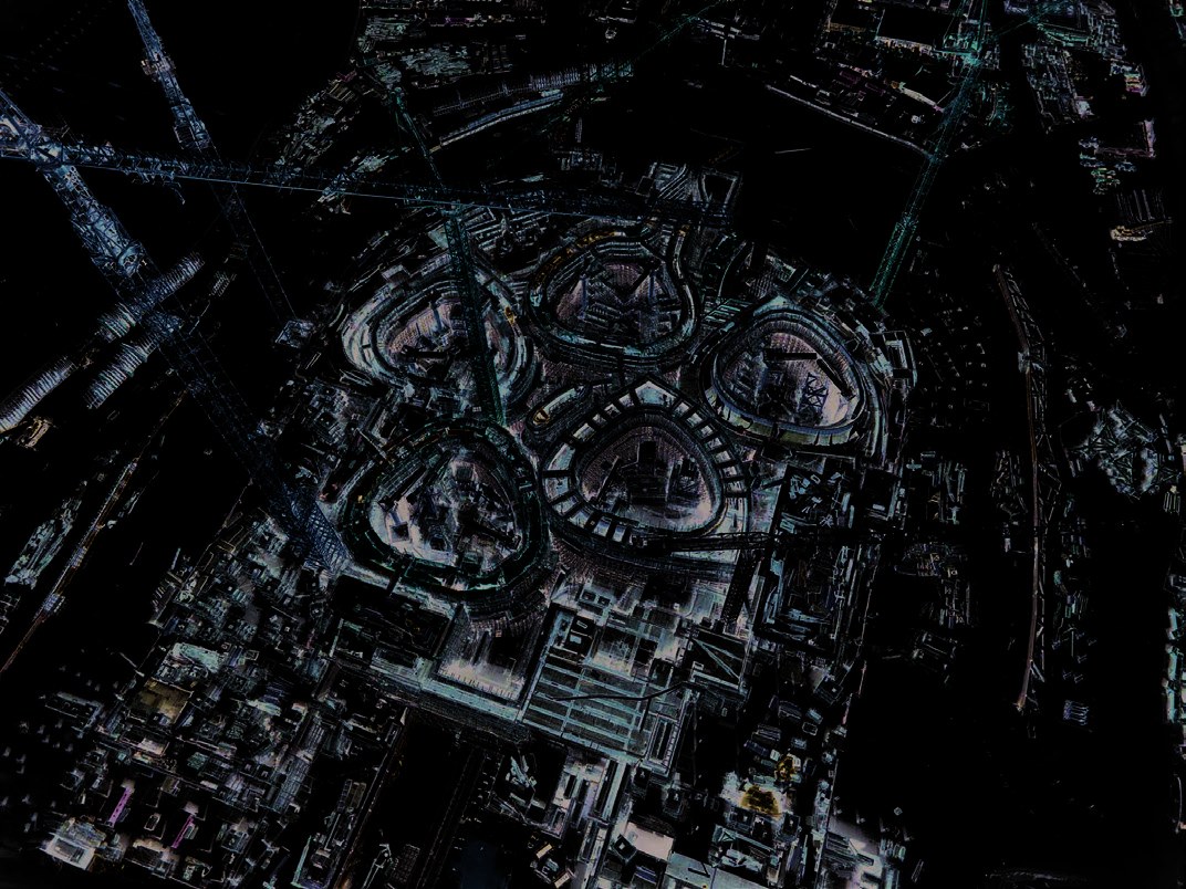
The Zayed National Museum, designed by Foster + Partners on Al Saadiyat Island’s Cultural District, is organized around a landscaped garden mound that references Sheikh Zayed’s connection to the natural environment. The five tower galleries rise from this mound like feathers — each one a steel structure enclosed in a perforated metal skin that responds to solar orientation.
The Geometry Problem
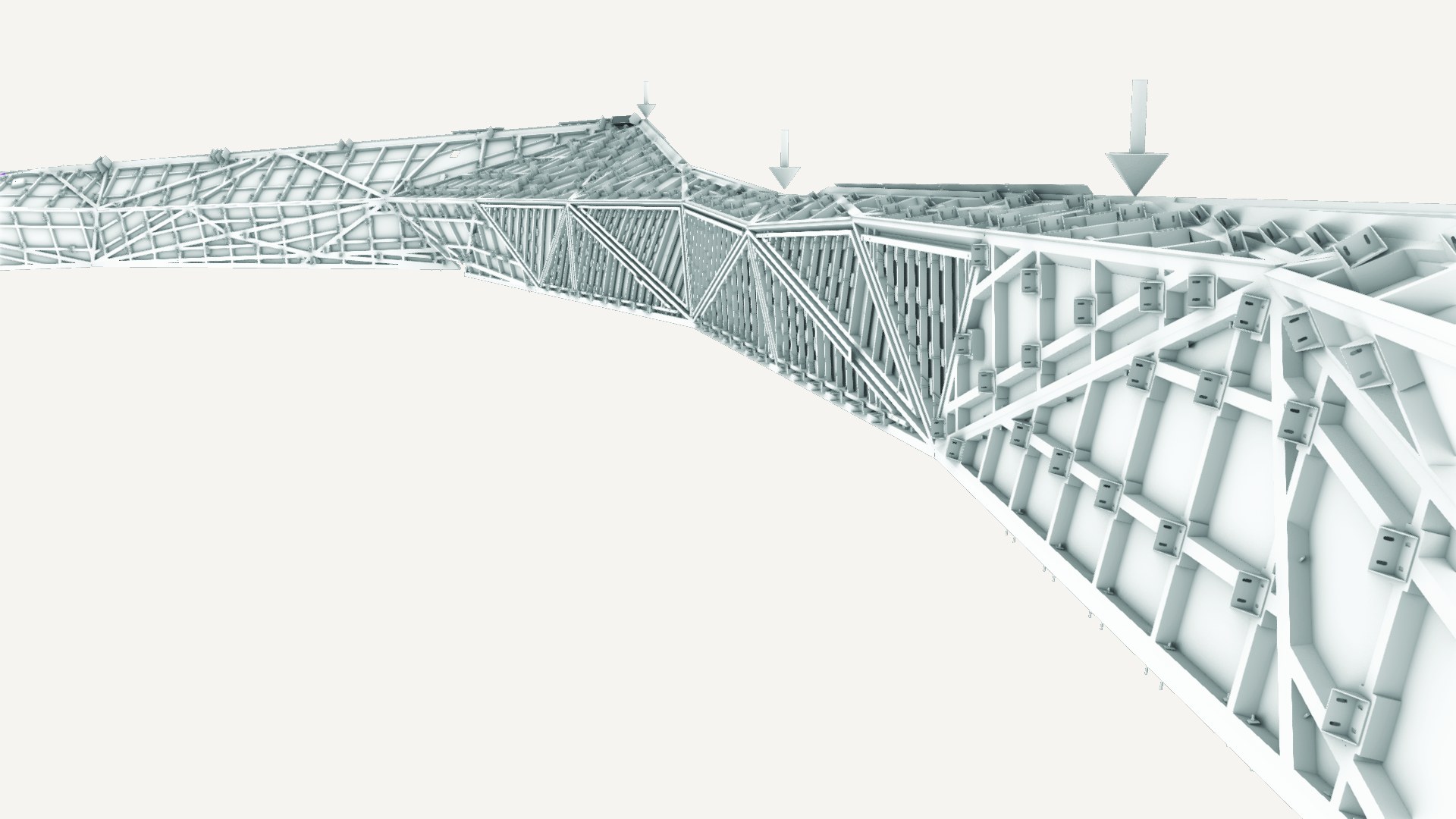
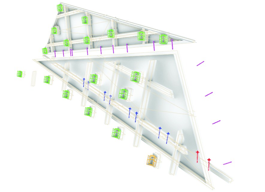
The museum’s exterior envelope presented one of the most geometrically complex challenges in the project: a fractal surface where every adjacent panel faces a different vector orientation. No two surfaces are parallel and no standard tiling logic applies — each triangulated panel is unique, requiring its own fabrication data.
Standard BIM workflows assume that surfaces can be addressed through repetition and mirroring. The mound’s fractal envelope breaks this assumption entirely.
Workflow: From Surface to Fabrication
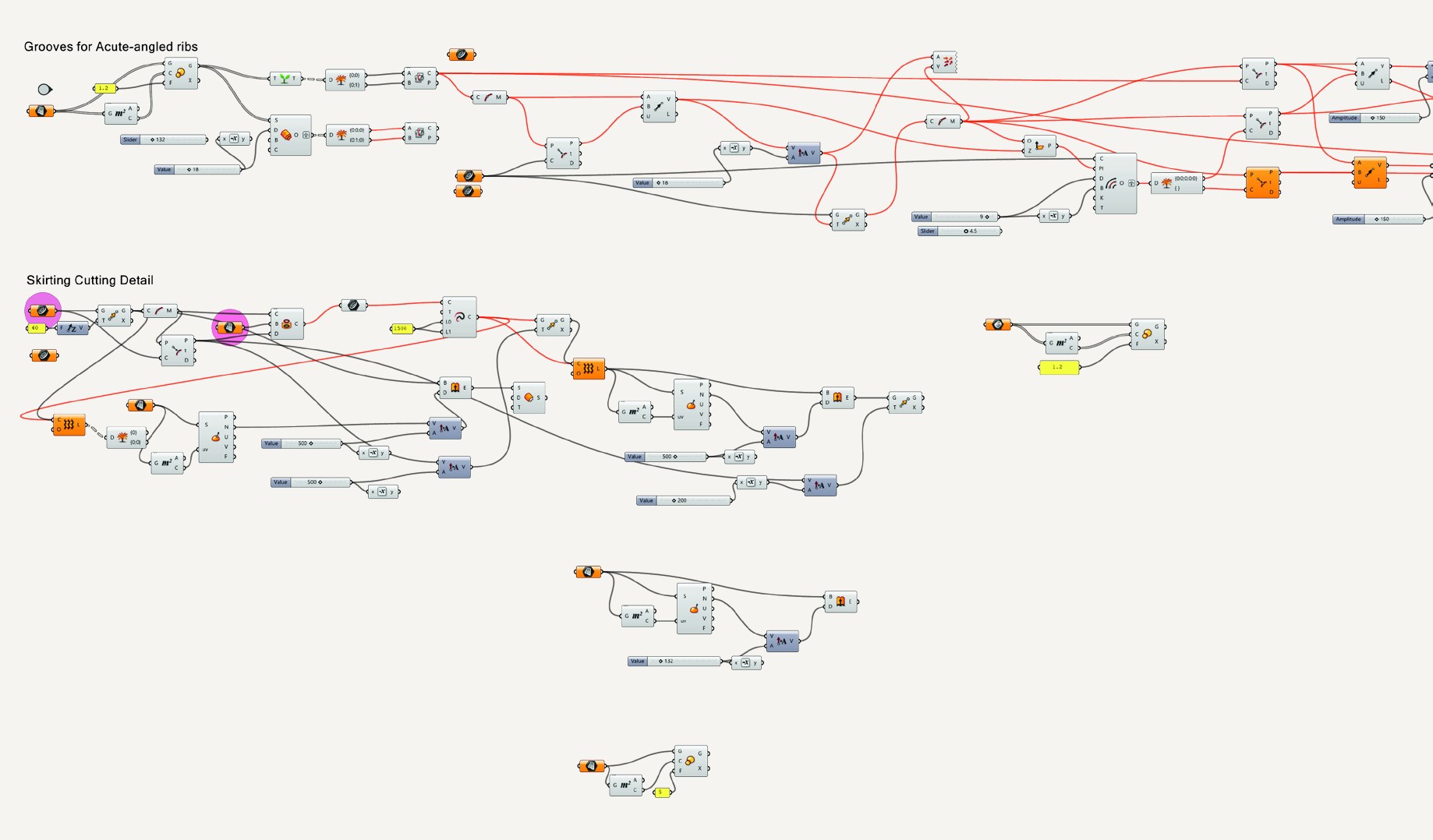
Resolving the geometry required building custom tools rather than adapting existing ones. The workflow combined Rhinoceros 3D for surface rationalization, Grasshopper for parametric component generation, and Rhino.Inside.Revit to bring the resolved geometry into the BIM environment as fully documented Revit families — ready for fabrication and coordination.
Each panel assembly was documented with its full component set: pins, peripheral ribs, mid ribs, sitting ribs, and bolted brackets. The Grasshopper scripts handled not just the geometry but the assembly logic — identifying which connection type applied to each surface condition and generating the correct components automatically.
Human UI: Making Complex Tools Accessible
To enable efficient collaboration across a multi-disciplinary team, a custom interface was developed using the Human UI plugin for Grasshopper. This allowed project managers and non-specialist team members to interact with the geometry scripts, adjust parameters, and review outputs without requiring direct access to the Grasshopper definition — reducing errors from manual input and accelerating the review cycle.
Coordination & Clash Detection
With the surface geometry resolved, full multi-discipline coordination was carried out in Autodesk Navisworks and BIM 360. The fractal geometry created a high density of potential clashes between the facade system and the structural elements beneath — the irregular panel orientations meant that standard clearance checks were insufficient. Systematic clash detection and iterative resolution was essential to maintaining the fabrication tolerances required for the panel assembly system.